0%

本文记录用LeCroy PCIe协议分析仪debug SD host controller issue的方法。具体背景是该issue使用windbg或者打开driver debug log后无法复现,只能用PCIe协议分析仪分析。

PCIe包解析的配置

使用spread view模式:

image-20231122144912104

数据解析方式使用小端(Little-endian)+ MSB(高bit解析)

寻找目标PCIe设备

本文的PCIe设备为SD host controller。

以下PCIe trace包含一次Memory read和Config read操作,以Memory read为例,一次通信流程是:

MRd 指定Address -> MRd ACK -> CpID包含设备返回的数据(98601217)-> CpID的ACK

image-20231122144334835

一般PCIe包开头会枚举设备,此CpID数据即目标设备的VendorID/DeviceID,反推出此设备在PCIe config space的mapping起始地址是0x51200000

那么SD host设备的register被mapping到哪里?这是由PCIe config space的BAR0/BAR1/…地址指定。

如下图,SD host controller register space起使于PCIe config space的0x51200000,其中的0x10~0x27 offset内的值即BAR0/BAR1/…空间的地址

image-20231122143946372

看PCIe包即可得到SD host controller的Bar0位于0x51201000,即PCIe config space的4KB位置。该空间包含SD host register(由该chip的设计决定)

SD command分析

既然已知SD host register,那么查找SD command,实际就是查找对SD command register (如下图0Eh)的Memory write操作,根据写入数据查看SD command index。

image-20231122150434747

具体包分析如下:

下图0x5120100C中的0x0C即SD host register 0x0C,其写入数据Dword的高16bit即0x0E,所以最高byte即代表command index,即0x19是SD Command25: 多block写。

image-20231122151211580

image-20231122151622555

如何查看该SD command是否正常完成:

查看中断状态register 0x30h, 一般正常完成会返回command complete/ transfer complete等正常状态;未完成一般有Error interrupt。

image-20231122151913284

对于error interrupt,在0x32(即0x30高16bit)查看具体类型:

image-20231122152004564下面两个CpID分别是正常返回和错误返回:

image-20231122152111371

image-20231122152045475

正常返回的0x32(0x30高16bit)全为0,错误返回非0;错误类型为ADMA error + CRC error (data 0x32 = 0x0220)

pip install换源

pip install,有的包一直timeout无法安装

1
ReadTimeoutError: HTTPSConnectionPool(host='files.pythonhosted.org', port=443): Read timed out

单次换源

使用 -i 指定国内源

1
pip install -i https://pypi.tuna.tsinghua.edu.cn/simple pyside6

常用源:

1
2
3
清华大学:https://pypi.tuna.tsinghua.edu.cn/simple
阿里云:http://mirrors.aliyun.com/pypi/simple
豆瓣:http://pypi.douban.com/simple

全局换源

windows下,直接在user目录中创建一个pip目录,如:C:\Users\用户名\pip,即 %HOMEPATH%\pip,然后新建文件pip.ini,输入以下内容(以tsinghua镜像为例):

1
2
3
4
[global]
index-url = https://pypi.tuna.tsinghua.edu.cn/simple
[install]
trusted-host = pypi.tuna.tsinghua.edu.cn

Linux下,配置~/.pip/pip.conf,内容和windows .ini内容一样

思维导图

advanced -> 使用central idea, sub-topic, branch绘制

image-20230920100931945

多种代码可视化分析工具What are the best code visualization and analysis tools?

Sourcetrail

官方文档:Sourcetrail/getting-started

使用方式:

(1) Linux kernel生成代码调用图

需要用bear编译kernel生成compile_commands.json作为索引数据库

1
bear -- make -j4

sourcetrail导入compile_commands.json之后即可索引源码,生成调用链图

Screenshot from 2023-09-18 16-19-29

(2) C++项目生成代码调用图

以Visual Studio编译的MFC项目为例,需要在Visual Studio安装sourcetrail插件:

1
Visual Studio->拓展->管理插件->联机VisualStudioMarket->搜索sourcetrail extension ->安装

安装之后生成database:

1
Visual Studio->拓展->sourcetrail -> Create compilation database

sourcetrail即可用compilation databas索引源码,生成调用链图:

image-20230918163406747

PCI tree结构

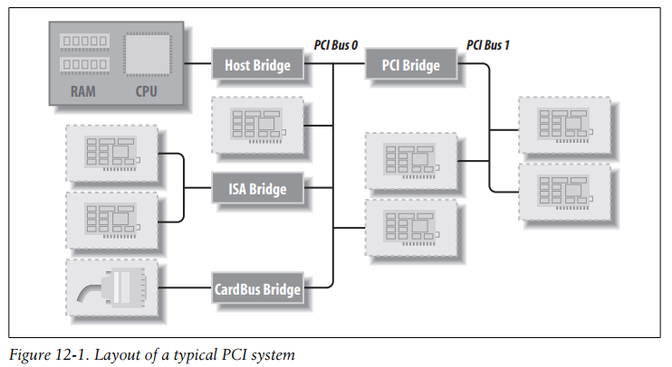
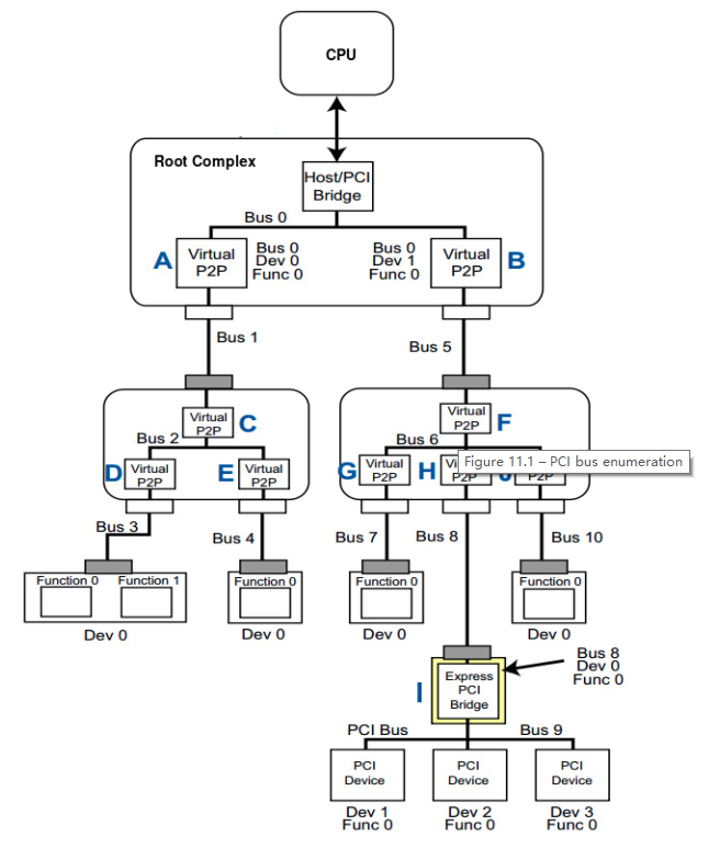
关于PCIe tree的bus/device的详细architecture,参考LDD3和Mastering Linux Device Driver Development - John Madieu

image-20230829111444515

image-20230829111727760

Root complex (RC): This refers to the PCIe host controller in the SoC. It can access the main memory without CPU intervening, which is a feature used by other devices to access the main memory. They are also known as Host-to-PCI bridges.

Bridges: These provide an interface to other buses, such as PCI or PCI X, or even another PCIe bus. A bridge can also provide an interface to the same bus

Endpoint (EP): Endpoints are PCIe devices, and are represented by type 00h configuration space headers. They never appear on a switch’s internal bus and have no downstream port

lspci使用示例

下面介绍如何找到一个PCI(e)设备的信息,及其上游端口信息,以及设备的register space内容

(1)查看所有pci设备:

1
2
3
4
5
6
7
8
9
10
11
12
13
cursorhu@ubuntu-PC:~$ lspci
00:00.0 Host bridge: Intel Corporation 11th Gen Core Processor Host Bridge/DRAM Registers (rev 01)
00:02.0 VGA compatible controller: Intel Corporation TigerLake-LP GT2 [Iris Xe Graphics] (rev 01)
00:04.0 Signal processing controller: Intel Corporation TigerLake-LP Dynamic Tuning Processor Participant (rev 01)
00:05.0 Multimedia controller: Intel Corporation Device 9a19 (rev 01)
00:07.0 PCI bridge: Intel Corporation Tiger Lake-LP Thunderbolt 4 PCI Express Root Port #0 (rev 01)
00:07.1 PCI bridge: Intel Corporation Tiger Lake-LP Thunderbolt 4 PCI Express Root Port #1 (rev 01)
00:07.2 PCI bridge: Intel Corporation Tiger Lake-LP Thunderbolt 4 PCI Express Root Port #2 (rev 01)
00:07.3 PCI bridge: Intel Corporation Tiger Lake-LP Thunderbolt 4 PCI Express Root Port #3 (rev 01)
...
00:1c.0 PCI bridge: Intel Corporation Tiger Lake-LP PCI Express Root Port #8 (rev 20)
...
a9:00.0 Non-Volatile memory controller: Device 0012:1cc1

(2)查看PCI设备上下游信息

下面关注PCIe device a9:00.0, 用 lspci -v (verbose)查看详细信息:

是一个nvme设备,使用的driver是nvme;device id是0012:1cc1

1
2
3
4
5
6
7
8
9
cursorhu@ubuntu-PC:~$ lspci -v
a9:00.0 Non-Volatile memory controller: Device 0012:1cc1 (prog-if 02 [NVM Express])
Subsystem: Device 3456:5344
Physical Slot: 7
Flags: bus master, fast devsel, latency 0, IRQ 19, NUMA node 0, IOMMU group 20
Memory at 88c00000 (64-bit, non-prefetchable) [size=16K]
Capabilities: <access denied>
Kernel driver in use: nvme
Kernel modules: nvme

查看这个设备的上游信息,包括它所在的PCIe bridge(即PCIe port,端口也是PCI设备)

如下lspci -t (tree)列出PCI tree,其中[]内的是bus号,-xx.x是设备号

1
2
3
4
5
6
7
8
9
10
11
12
13
14
cursorhu@ubuntu-PC:~$ lspci -t
-[0000:00]-+-00.0
+-02.0
+-04.0
+-05.0
+-07.0-[01-2a]--
+-07.1-[2b-54]--
+-07.2-[55-7e]--
+-07.3-[7f-a8]--
....
+-1c.0-[a9]----00.0
+-1d.0-[aa]--
....
\-1f.6

我们关注的设备a9:00.0表示该设备的 bus是a9, device是00.0,对应PCI tree的 [a9]—-00.0

其上游设备是1c.0,完整设备号为00:1c.0,是个PCIe bridge;每个bridge都是PCIe设备,只不过它比较特殊,是连接其他PCIe设备的设备。根据lspci信息查看该PCIe bridge为:

1
00:1c.0 PCI bridge: Intel Corporation Tiger Lake-LP PCI Express Root Port #8 (rev 20)

PCIe bridge的更上游即bus 00,是PCIe RC (root complex)

上图中有的bridge可以支持一定范围的bus号,例如bus范围为01-2a:

1
+-07.0-[01-2a]--

(3)查看PCI设备的register space

使用lspci -s [bus]:[device].[function] -xxxx 查看完整的PCIe register space(需要root权限), -s: show, lspci --help查看各选项

1
2
3
4
5
6
7
8
9
10
11
12
13
14
15
16
17
18
19
20
21
22
23
cursorhu@ubuntu-PC:~$ sudo lspci -s 00:1c.0 -xxxx (或者-xxx,显示00~ff)
[sudo] password for cursorhu:
00:1c.0 PCI bridge: Intel Corporation Tiger Lake-LP PCI Express Root Port #8 (rev 20)
00: 86 80 bf a0 07 04 10 00 20 00 04 06 00 00 81 00
10: 00 00 00 00 00 00 00 00 00 a9 a9 00 40 40 00 20
20: c0 88 50 89 01 7e 91 7e 60 00 00 00 60 00 00 00
30: 00 00 00 00 40 00 00 00 00 00 00 00 ff 04 02 00
40: 10 80 42 01 01 80 00 00 20 00 11 00 13 4c 72 08
50: 42 00 13 70 60 b2 3c 00 08 10 40 00 08 00 00 00
60: 00 00 00 00 37 08 00 00 00 04 00 00 0e 00 00 00
70: 03 00 1f 00 00 00 00 00 00 00 00 00 00 00 00 00
80: 05 90 01 00 78 02 e0 fe 00 00 00 00 00 00 00 00
90: 0d a0 00 00 00 00 00 00 00 00 00 00 00 00 00 00
a0: 01 00 03 c8 00 00 00 00 00 00 00 00 00 00 00 00
b0: 00 00 00 00 00 00 00 00 00 00 00 00 00 00 00 00
c0: 00 00 00 00 00 00 00 00 00 00 00 00 00 00 00 00
d0: 11 10 00 07 42 18 01 40 0a 00 9e 09 00 00 00 00
e0: 00 03 e3 00 03 90 03 90 16 00 10 00 00 00 00 00
f0: 50 01 00 00 00 00 00 4c b5 0f 21 01 04 00 00 84
100: 01 00 01 22 00 00 00 00 00 40 00 00 11 00 06 00
110: 01 20 00 00 00 20 00 00 00 00 00 00 00 00 00 00
120: 00 00 00 00 00 00 00 00 00 00 00 00 00 00 00 00
...

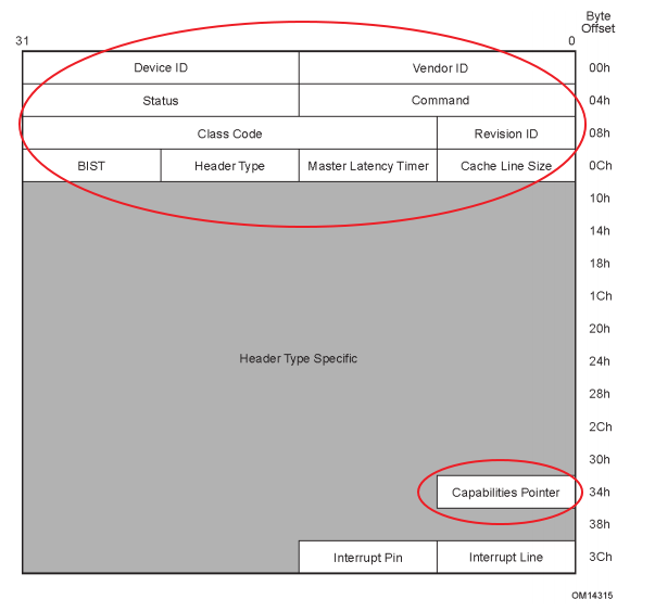
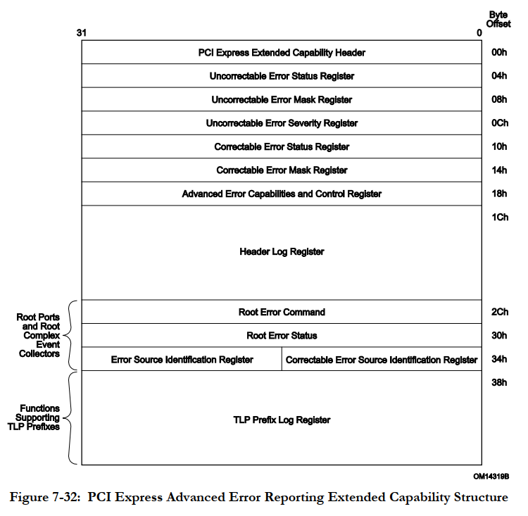
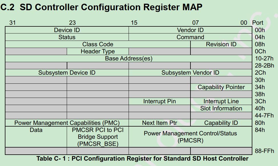
我们要确认PCI bridge的 link status register(位于capability register offset 0x12, bit 13 Link active bit) 以知道 PCIe link 是否 active.
如何查看:如下图 0x00 ~ 0x3C 是config space标准空间;0x34 capability pointer是地址,指向capability register空间,其值为0x40,因此capability register空间是从0x40开始;因此 link status regsiter 是 0x40+0x12 = 0x52, 其bit13 即 0x53 的 bit5.

详细register mapping参考PCI Express Base Spec.

image-20230829112915119

PCI device的创建过程

参考LDD3 LDM(Linux Device Model)

PCI device包括PCI driver, PCI core driver, Kobject三个层次,并在用户层sysfs反映device和driver。

image-20230830170650433

使用sysfs操作pci device

(1)使用/sys/bus/pci文件接口对device操作:

remove设备:

1
echo 1 > /sys/bus/pci/devices/AAAA:BB:CC.D/remove

AAAA:BB:CC.D为bus-info,分别为Domain:Bus:Device.Function

rescan设备

1
echo 1 > /sys/bus/pci/rescan

reset设备

1
echo 1 > /sys/bus/pci/devices/AAAA:BB:CC.D/reset

(2) lspci & dmesg & 源码 分析:

首先lspci设备,以设备03:00.0 (SD Host controller)为例

1
2
3
4
5
cursorhu@ubuntu-PC:~/linuxkernel/linux-6.2$ lspci
...
00:1c.7 PCI bridge: Intel Corporation Cannon Lake PCH PCI Express Root Port #8 (rev f0)
...
03:00.0 SD Host controller: O2 Micro, Inc. Device 9862 (rev 01)

remove设备:

非root用户执行时需要用sudo sh -c “命令内容”

1
sudo sh -c "echo 1 > /sys/bus/pci/devices/0000:03:00.0/remove"

dmesg显示remove调用了该device driver的 .remove

1
[ 241.962185] BHT-OSENTRY: BHT sd remove begin

remove之后lspci看不到设备03:00.0,lspci -t可见其bus号03下挂的设备为空

1
2
3
4
5
6
7
8
9
10
11
12
13
14
15
16
17
cursorhu@ubuntu-PC:~/linuxkernel/linux-6.2$ lspci -t
-[0000:00]-+-00.0
+-02.0
+-12.0
+-14.0
+-14.2
+-16.0
+-17.0
+-1b.0-[01]--
+-1c.0-[02]--
+-1c.7-[03]--
+-1d.0-[04]--
+-1f.0
+-1f.3
+-1f.4
+-1f.5
\-1f.6

rescan设备:

1
sudo sh -c "echo 1 > /sys/bus/pci/rescan"

lspci -t可见其bus号03下挂的设备为为00.0,即设备的[bus:device.function]为03:00.0

1
2
3
4
5
6
7
8
9
10
11
12
13
14
15
16
-[0000:00]-+-00.0
+-02.0
+-12.0
+-14.0
+-14.2
+-16.0
+-17.0
+-1b.0-[01]--
+-1c.0-[02]--
+-1c.7-[03]----00.0
+-1d.0-[04]--
+-1f.0
+-1f.3
+-1f.4
+-1f.5
\-1f.6

dmesg显示rescan调用了该device driver的 .probe

1
[ 617.171735] BHT-OSENTRY: BHT sd probe begin

reset设备:

备份设备的config register 0x0~0x3C,然后调用pci_dev_restore:

1
2
* This function does not just reset the PCI portion of a device, but
* clears all the state associated with the device.
1
2
3
4
5
6
7
8
9
10
11
12
13
14
15
16
17
18
19
20
21
22
[ 1116.993784] bht-sd 0000:03:00.0: saving config space at offset 0x0 (reading 0x98621217)
[ 1116.993790] bht-sd 0000:03:00.0: saving config space at offset 0x4 (reading 0x100406)
[ 1116.993793] bht-sd 0000:03:00.0: saving config space at offset 0x8 (reading 0x8050101)
[ 1116.993796] bht-sd 0000:03:00.0: saving config space at offset 0xc (reading 0x10)
[ 1116.993798] bht-sd 0000:03:00.0: saving config space at offset 0x10 (reading 0x51100000)
[ 1116.993801] bht-sd 0000:03:00.0: saving config space at offset 0x14 (reading 0x51101000)
[ 1116.993804] bht-sd 0000:03:00.0: saving config space at offset 0x18 (reading 0x0)
[ 1116.993806] bht-sd 0000:03:00.0: saving config space at offset 0x1c (reading 0x0)
[ 1116.993809] bht-sd 0000:03:00.0: saving config space at offset 0x20 (reading 0x0)
[ 1116.993811] bht-sd 0000:03:00.0: saving config space at offset 0x24 (reading 0x0)
[ 1116.993813] bht-sd 0000:03:00.0: saving config space at offset 0x28 (reading 0x0)
[ 1116.993816] bht-sd 0000:03:00.0: saving config space at offset 0x2c (reading 0x21217)
[ 1116.993818] bht-sd 0000:03:00.0: saving config space at offset 0x30 (reading 0x0)
[ 1116.993821] bht-sd 0000:03:00.0: saving config space at offset 0x34 (reading 0x6c)
[ 1116.993823] bht-sd 0000:03:00.0: saving config space at offset 0x38 (reading 0x0)
[ 1116.993826] bht-sd 0000:03:00.0: saving config space at offset 0x3c (reading 0x10b)
[ 1118.015083] pcieport 0000:00:1c.7: re-enabling LTR
[ 1118.015133] bht-sd 0000:03:00.0: restoring config space at offset 0x3c (was 0x100, writing 0x10b)
[ 1118.015170] bht-sd 0000:03:00.0: restoring config space at offset 0x14 (was 0x0, writing 0x51101000)
[ 1118.015191] bht-sd 0000:03:00.0: restoring config space at offset 0x10 (was 0x0, writing 0x51100000)
[ 1118.015205] bht-sd 0000:03:00.0: restoring config space at offset 0xc (was 0x0, writing 0x10)
[ 1118.015227] bht-sd 0000:03:00.0: restoring config space at offset 0x4 (was 0x100000, writing 0x100406)

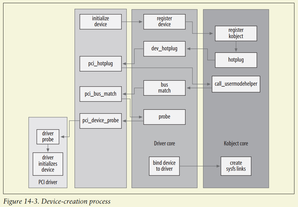
PCI driver的register access API分析

API在LDD3的PCI driver一章已经有较详细说明:

*Linux offers a standard interface to access the configuration space.
As far as the driver is concerned, the configuration space can be accessed through 8-
bit, 16-bit, or 32-bit data transfers. The relevant functions are prototyped in <linux/*
pci.h>

1
2
3
4
5
6
int pci_read_config_byte(struct pci_dev *dev, int where, u8 *val);
int pci_read_config_word(struct pci_dev *dev, int where, u16 *val);
int pci_read_config_dword(struct pci_dev *dev, int where, u32 *val);
int pci_write_config_byte(struct pci_dev *dev, int where, u8 val);
int pci_write_config_word(struct pci_dev *dev, int where, u16 val);
int pci_write_config_dword(struct pci_dev *dev, int where, u32 val);

内部实现实际是pci_bus_read_config_word,参考:access.c#L554

1
2
3
4
5
6
7
8
9
int pci_read_config_word(const struct pci_dev *dev, int where, u16 *val)
{
if (pci_dev_is_disconnected(dev)) {
PCI_SET_ERROR_RESPONSE(val);
return PCIBIOS_DEVICE_NOT_FOUND;
}
return pci_bus_read_config_word(dev->bus, dev->devfn, where, val);
}
EXPORT_SYMBOL(pci_read_config_word);

pci_bus_read_config_word的内部实现LDD3也说了:

The actual implementation of pci_read_config_byte(dev, where, val), for instance, expands to:
dev->bus->ops->read(bus, devfn, where, 8, val);

其中bus->ops使用pci_ops结构:

1
2
3
4
5
6
struct pci_ops {
int (*read)(struct pci_bus *bus, unsigned int devfn, int where, int size,
u32 *val);
int (*write)(struct pci_bus *bus, unsigned int devfn, int where, int size,
u32 val);
};

pci_read_config_byte的实现是宏函数,使用##连接符动态定义byte, word, dword,因此直接搜索不到,实际还是在access.c#L74,就在EXPORT_SYMBOL(pci_bus_read_config_word); 的前面定义:

1
2
3
4
5
6
7
8
9
10
11
12
13
14
15
16
17
#define PCI_OP_READ(size, type, len) \
int noinline pci_bus_read_config_##size \
(struct pci_bus *bus, unsigned int devfn, int pos, type *value) \
{ \
int res; \
unsigned long flags; \
u32 data = 0; \
if (PCI_##size##_BAD) return PCIBIOS_BAD_REGISTER_NUMBER; \
pci_lock_config(flags); \
res = bus->ops->read(bus, devfn, pos, len, &data); \
if (res) \
PCI_SET_ERROR_RESPONSE(value); \
else \
*value = (type)data; \
pci_unlock_config(flags); \
return res; \
}

那么bus->ops->read的底层实现到底是什么?取决于cpu和pci架构,例如arm/x86/ia64…

全局搜索定义struct pci_ops的代码即可见,以x86为例

1
2
3
4
5
6
7
8
9
10
11
12
13
14
15
16
17
18
19
20
struct pci_ops pci_root_ops = {
.read = pci_read,
.write = pci_write,
};

static int pci_read(struct pci_bus *bus, unsigned int devfn, int where, int size, u32 *value)
{
return raw_pci_read(pci_domain_nr(bus), bus->number,
devfn, where, size, value);
}

int raw_pci_read(unsigned int domain, unsigned int bus, unsigned int devfn,
int reg, int len, u32 *val)
{
if (domain == 0 && reg < 256 && raw_pci_ops)
return raw_pci_ops->read(domain, bus, devfn, reg, len, val);
if (raw_pci_ext_ops)
return raw_pci_ext_ops->read(domain, bus, devfn, reg, len, val);
return -EINVAL;
}

struct pci_raw_ops有几处定义,direct.c, mmconfig_32.c, mmconfig_64.c, 分别对应不同的访问方式。下面以direct.c中的实现为例:

1
2
3
4
5
6
7
8
9
const struct pci_raw_ops pci_direct_conf1 = {
.read = pci_conf1_read,
.write = pci_conf1_write,
};

static const struct pci_raw_ops pci_direct_conf2 = {
.read = pci_conf2_read,
.write = pci_conf2_write,
};

有两种direct config访问方式,区别在于指令结构不一样,参考PCI express base spec 的 Configuration Space Header。

1
2
3
4
5
6
7
8
9
10
11
12
13
14
/*
* Functions for accessing PCI base (first 256 bytes) and extended
* (4096 bytes per PCI function) configuration space with type 1
* accesses.
*/

#define PCI_CONF1_ADDRESS(bus, devfn, reg) \
(0x80000000 | ((reg & 0xF00) << 16) | (bus << 16) \
| (devfn << 8) | (reg & 0xFC))

/*
* Functions for accessing PCI configuration space with type 2 accesses
*/
#define PCI_CONF2_ADDRESS(dev, reg) (u16)(0xC000 | (dev << 8) | reg)

以pci_conf1_read的内部实现为例:

1
2
3
4
5
6
7
8
9
10
11
12
13
14
15
16
17
18
19
20
21
22
23
24
25
26
27
28
29
30
static int pci_conf1_read(unsigned int seg, unsigned int bus,
unsigned int devfn, int reg, int len, u32 *value)
{
unsigned long flags;

if (seg || (bus > 255) || (devfn > 255) || (reg > 4095)) {
*value = -1;
return -EINVAL;
}

raw_spin_lock_irqsave(&pci_config_lock, flags);

outl(PCI_CONF1_ADDRESS(bus, devfn, reg), 0xCF8);

switch (len) {
case 1:
*value = inb(0xCFC + (reg & 3));
break;
case 2:
*value = inw(0xCFC + (reg & 2));
break;
case 4:
*value = inl(0xCFC);
break;
}

raw_spin_unlock_irqrestore(&pci_config_lock, flags);

return 0;
}

最底层调用的是x86的in, out汇编指令,也是宏函数封装,参考arch/x86/include/asm/shared/io.h#L27

1
2
3
4
5
6
7
8
9
10
11
12
13
static __always_inline void __out##bwl(type value, u16 port)		\
{ \
asm volatile("out" #bwl " %" #bw "0, %w1" \
: : "a"(value), "Nd"(port)); \
} \
\
static __always_inline type __in##bwl(u16 port) \
{ \
type value; \
asm volatile("in" #bwl " %w1, %" #bw "0" \
: "=a"(value) : "Nd"(port)); \
return value; \
}

至此pci_read_config_byte一类的PCI register acess API分析完毕。

PCIe AER driver分析和debug记录

AER: Advanced Error Reporting

PCIe的AER是PCIe spec协议的标准功能,AER涉及到Error信号产生,上报,处理,错误恢复等。

PCIe base spec摘要:

Error分类:

image-20230825171440881

Error信号在数字逻辑的处理流水:

image-20230825171423678

AER的capability regsiter:

image-20230825171511047

PCIe AER driver摘要

PCIe driver的使用aer service driver实现软件处理流程,aer service属于PCIe bus driver的子功能,而PCIe driver又属于PCI driver字类。

什么是PCIe service driver: 2. The PCI Express Port Bus Driver Guide HOWTO

什么是PCIe AER driver: 8. The PCI Express Advanced Error Reporting Driver Guide HOWTO

PCIe AER driver在Kconfig的开关

配置Kconfig可开关:make menuconfig -> / -> 搜索PCIEAER -> n关闭,y打开

如下Kconfig的AER三个相关项都被关闭:

1
2
3
CONFIG_PCIAER=n
CONFIG_ACPI_APEI_PCIEAER=n
CONFIG_PCIAER_INJECT=n

image-20230825175611772

示例:ACS violation error的debug过程

在调试SD express host controller driver过程中,发现部分SD express card(ADATA & Lexar)在linux下无法正常初始化,windows下正常。以下为issue debug过程。

(1)首先打开PCI driver的debug打印

1
make menuconfig -> /搜索 -> PCI_DEBUG -> y

参考Linux driver常用调试技术记录

(2)对比Good Case和Bad case

SD express card的切换是包含PCIe linkdown和linkup的过程,会有两次hot-plug中断处理。

Bad case的log中,发现如下两种AER error report:

image-20230829114906631

a. RxErr

1
2
3
4
5
Link Training Error:一插卡就有此error. 此error发生在hot-plug中断之前
[ 106.119856] pcie port 0000:00:1b.4: pciehp: pending interrupts 0x0100 from Slot Status
[ 106.119863] pcieport 0000:00:1b.4: PCIe Bus Error: severity=Corrected, type=Physical Layer, (Receiver ID) //PCI driver检测到error属于Physical Layer
[ 106.119864] pcieport 0000:00:1b.4: device [8086:43c4] error status/mask=00000001/00002000 //error status bit0 =1
[ 106.119866] pcieport 0000:00:1b.4: [ 0] RxErr (First) //error的含义:在old version of PCIe spec表示Link Training Error.

b. ACS Violation

1
2
3
4
5
6
7
 ACS Violation error: 在hot-plug driver检测到hot-plug中断之后正在处理hot-plug的card/link状态检测过程中,PCIe driver检测到此error
[ 107.493928] enter pciehp_ist
[ 107.494136] pcieport 0000:00:1b.4: DPC: containment event, status:0x1f01 source:0x0000
[ 107.494140] pcieport 0000:00:1b.4: DPC: unmasked uncorrectable error detected //PCI driver检测到error
[ 107.494145] pcieport 0000:00:1b.4: PCIe Bus Error: severity=Uncorrected (Non-Fatal), type=Transaction Layer, (Receiver ID) //PCI driver检测到error属于Transaction Layer
[ 107.494148] pcieport 0000:00:1b.4: device [8086:43c4] error status/mask=00200000/00004000 //error status bit21 =1
[ 107.494151] pcieport 0000:00:1b.4: [21] ACSViol (First) //error的含义:ACS Violation

在此ACS error发生之后,hot-plug driver检测不到LinkUp(1st 检测), polling 10s后也检测不到LinkUp(2nd 检测),最终打印No link,PCIe设备未启动configuration。

(3) ACS violation分析

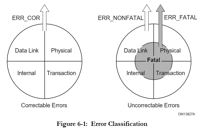
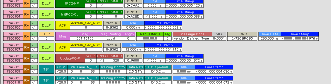
PCIe协议分析抓包发现一个可疑的vendor defined message,可能是对应上述错误信息:

image-20230829115802177

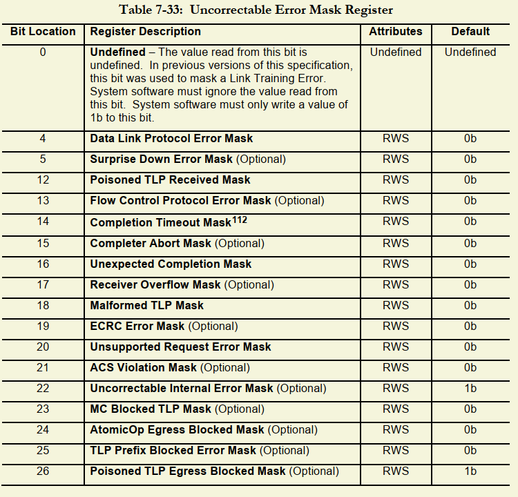
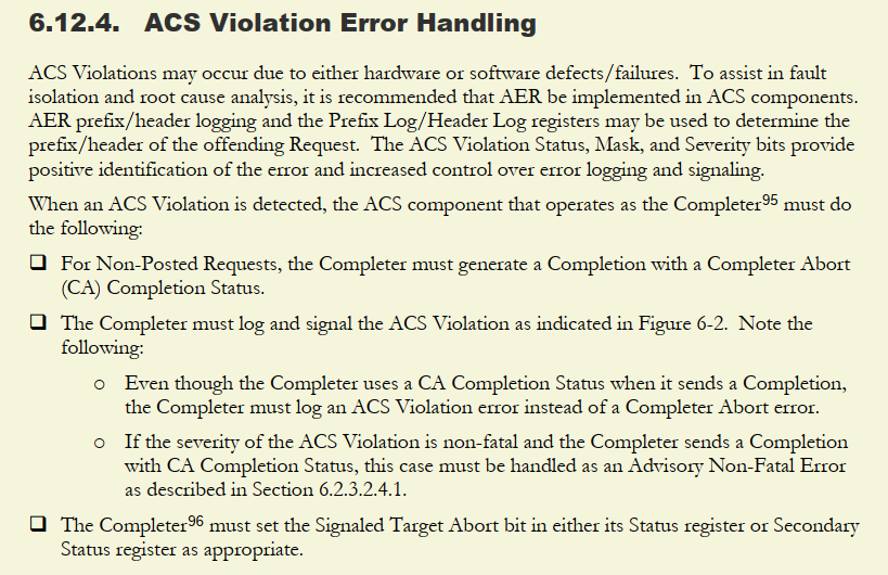
ACS violation在PCIe spec描述如下:

image-20230829115115392

(4)原因和解决办法

逻辑链:PCIe Link training到L0之后,PCI driver还没发送Config Write操作定义Bus number的时候, SD express卡就发送了一个Vendor Specific defined message,这个是违反spec规定的;而RC side ACS 功能是enable的,会检测收到的包中的bus number是否和自己已扫描的bus相符,如果不符就报错ACS violation,并放弃卡初始化。

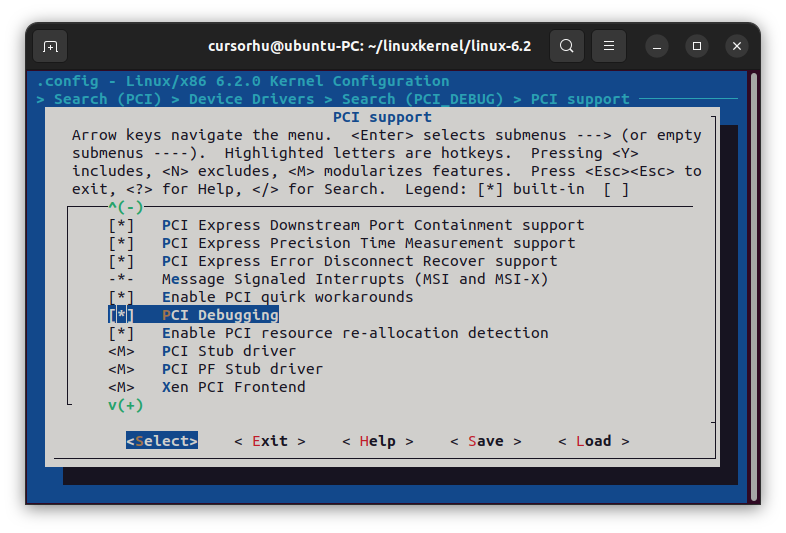
解决办法(workaround):关闭PCIe bridge driver的ACS enable bit (ACS Control register bit0=1’b0):

具体代码改动为:

1). drivers/pci/pci.c -> pci_std_enable_acs :pcie默认enable ACS Control register的ACS violation bit,此处修改为disable ACS violation bit.

2). drivers/pci/quirk.c -> pci_quirk_enable_intel_spt_pch_acs: 此处为Intel PCIe的特有配置,此处也 disable ACS violation bit

设置sudo

普通用户(以username为例)并没有被加入sudo用户组,不能使用sudo命令

1
2
username@debian:~$ sudo apt install xxx
username is not in the sudoers file.

有两种方式:

  1. 在su下用visudo(nano也可以)编辑/etc/sudoers文件,新增username使sudo能获取root权限。

    1
    2
    3
    # User privilege specification
    root ALL=(ALL:ALL) ALL
    username ALL=(ALL:ALL) ALL
  2. 在su下用usermod -aG sudo username,将username添加到sudo组,由于/etc/sudoers的如下设置已经将sudo组设为root权限,所以这个操作等效于使username能用sudo获取root权限。

    1
    %sudo ALL=(ALL:ALL) ALL
  • sbin的命令not found问题:执行visudo或usermod时,发现command not found. Debug过程如下:

​ 使用whereis visudo查看路径是/usr/sbin;echo $PATH没有/usr/sbin,因此是环境变量问题。

方式一:在username的~/.bashrc下添加sbin到PATH,生效之后sbin目录的命 令才可执行:

1
2
3
4
nano .bashrc
export PATH=$PATH:/usr/sbin
source ~/.bashrc
echo $PATH

方式二:另外一种方式是加软链接,需要一个个添加

1
ln -s /usr/sbin/visudo /usr/bin/visudo
  • 如何退出su:使用exit,或su username,切换到username用户

设置apt源

  • 使用iso安装的debian,首先需要取消从iso安装软件的选项:

​ software&update -> Other Software -> 取消勾选cdrom

  • 再选择国内源, 例如China-> mirrors.163.com/debian,并选中main/free/non-free各种下载选项。
  • 如果refresh cache界面卡死,使用apt update手动更新源。

设置gnome shell

gnome shell即gnome的桌面

(1)通过extensions自定义桌面插件

参考:How to Use GNOME Shell Extensions [Complete Guide]

可以通过gnome-shell-extension-manager直接安装extension,无需到网站下载

1
sudo apt install gnome-shell-extension-manager

推荐安装Dash to Dock和Arc Menu

(2)修改主题(theme)

参考 How to Install and Change GNOME Theme in Linux

打开extensions的User Themes插件后才可以安装自定义themes

手动安装单个GTK主题的方法:

1
2
3
4
5
#创建放置themes的目录
mkdir ~/.themes
#从gnome-look下载themes,放到.themes目录,Ctrl+H打开隐藏目录
https://www.gnome-look.org/browse/
#打开gnome tweak(默认已安装),Appearance -> Shell -> 使用themes

注意

  • 要完整桌面主题效果,需要安装gtk-theme,icon-theme,cursor-theme等多类theme。例如WhileSur,要达到和MacOS一样的效果,需要去GTK3/4 themes, Full Icon Themes,Cursors分别下载top5的WhileSur主题。一个主题可能有多种模式,按github install.sh能完整安装各种模式,手动下载只能安装一种模式。
  • 注意gnome桌面是基于GTK,GTK is a multi-platform toolkit for creating graphical user interfaces. 所以是在gtk-theme而不是gnome-shell找。
  • 要自定义登录界面的主题,去GDM themes找top5(改GDM需要先安装loginized);要自定义GRUB主题,去GRUB themes找。
  • Top 10 themes: best-gtk-themes

Printk详解

printk参考Kernel document: 使用printk记录消息

其中printk是一组4个值,分别是:current, default, minimumboot-time-default. 调试打印一般只配置current和boot-time-default = 7 (支持< pr_debug的打印)或者8 (支持= pr_debug的打印).

printk的基础用法

常用示例如下,一般是手动添加打印代码时使用:

1
2
step1: 例如要打印当前函数被调用,添加pr_info("%s\n", __FUNCTION__)
step2: echo 7 > /proc/sys/kernel/printk

Tips1: 非root用户不能成功执行sudo echo 7 > /proc/sys/kernel/printk,显示permission denied

原因:因为sudo仅让echo按root权限执行,没有让>按root权限执行

解决办法一:sudo su进入root用户

解决办法二:dmesg配置printk级别:sudo dmesg -n 7

解决办法三:解决任何sudo echo写入的权限问题:

sudo sh -c "cmd",让bash将整个cmd字符串当一个命令执行,并赋予root权限

1
sudo sh -c "echo 7 > /proc/sys/kernel/printk"

cat /proc/sys/kernel/printk可见printk已变成7,4,1,7(默认是4,4,1,7)

Tips2: (printk持久化)系统启动自动设置打印级别:

/proc/sys/kernel/printk每次启动后都恢复为默认值4,4,1,7.

在/etc/sysctl.conf添加kernel.printk可以系统启动时自动配置打印级别, 通常用于记录kernel boot阶段的打印:

1
2
sudo vim /etc/sysctl.conf
kernel.printk = 8 4 1 8 #8: 打开包括pr_debug的所有打印级别

小结:

如果要观测系统启动中的driver debug打印,必须/etc/sysctl.conf配置kernel.printk

如果要观测系统启动后的driver debug打印,建议使用dmesg -n修改printk

printk在driver subsystem中的使用

Linux driver子系统通常使用printk的封装版。以pci driver为例,pci driver代码已经提供了pci_dbg, pci_info, pci_err等打印函数,其不仅打印arg信息,也打印pci port设备信息,例如以下PCIe driver的log:

pcieport 0000:00:1b.4 显示了当前的PCIe port。如果有多个PCIe port的打印,可以区分是哪个port的打印输出。

1
2
3
4
5
[   44.713266] pcieport 0000:00:1b.4: DPC: containment event, status:0x1f01 source:0x0000
[ 44.713268] pcieport 0000:00:1b.4: DPC: unmasked uncorrectable error detected
[ 44.713274] pcieport 0000:00:1b.4: PCIe Bus Error: severity=Uncorrected (Non-Fatal), type=Transaction Layer, (Receiver ID)
[ 44.713277] pcieport 0000:00:1b.4: device [8086:43c4] error status/mask=00200000/00004000
[ 44.713280] pcieport 0000:00:1b.4: [21] ACSViol (First)

如何设置dev_info, dev_err:

pci_info, pci_err的打开和pr_info, pr_err一致,只需要设置打印级别大于info/err即可:

1
echo 7 > /proc/sys/kernel/printk

其他驱动模块的xxx_info, xxx_err也是一样

如何设置dev_dbg:

dev_dbg是比较特殊但常用的打印方式,定义如下。

可见dev_dbg的开启依赖于两个条件:

  • driver定义了CONFIG_DYNAMIC_DEBUG 或者 DEBUG 宏才能开启,一般使用DEBUG宏

  • printk级别需要为8(7为debug level, 8 > debug level,才能开启debug打印)

1
2
3
4
5
6
7
8
9
10
11
12
13
14
15

#if defined(CONFIG_DYNAMIC_DEBUG) || \
(defined(CONFIG_DYNAMIC_DEBUG_CORE) && defined(DYNAMIC_DEBUG_MODULE))
#define dev_dbg(dev, fmt, ...) \
dynamic_dev_dbg(dev, dev_fmt(fmt), ##__VA_ARGS__)
#elif defined(DEBUG)
#define dev_dbg(dev, fmt, ...) \
dev_printk(KERN_DEBUG, dev, dev_fmt(fmt), ##__VA_ARGS__)
#else
#define dev_dbg(dev, fmt, ...) \
({ \
if (0) \
dev_printk(KERN_DEBUG, dev, dev_fmt(fmt), ##__VA_ARGS__); \
})
#endif

以pci_dbg为例(内部实现是dev_dbg),要打开pci_dbg设置如下:

1
2
3
4
5
6
7
在Kernel Makefile定义DEBUG宏,可以在driver/pci的Makefile定义,也可以在Kernel根目录Makefile定义:

方式一:DEBUG宏定义在KCFLAG,即编译此目录的任何driver .o, .ko都定义了DEBUG宏
KCFLAGS += -DDEBUG

方式二:DEBUG宏定义在某一个driver模块,即编译此模块时定义了DEBUG宏,例如
obj-${CONFIG_PCI} += -DDEBUG

以上是对任意Driver模块打开DEBUG宏的通用方法;实际上drivers/pci已经定义了KCONFIG可选项如下,只需要make menuconfig时设置PCI_DEBUG = y 即可对drivers/pci的当前目录和子目录的模块编译都定义DEBUG宏:

1
2
3
4
5
6
7
8
9
10
11
12
13
### Makefile:
subdir-ccflags-$(CONFIG_PCI_DEBUG) := -DDEBUG

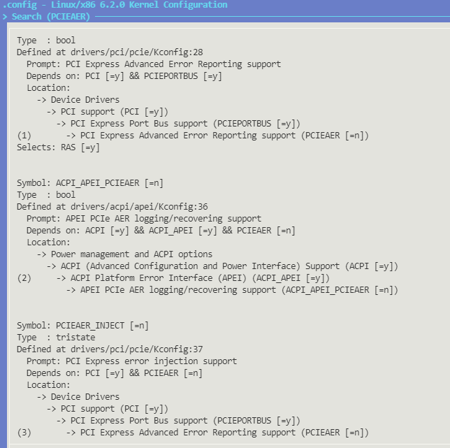
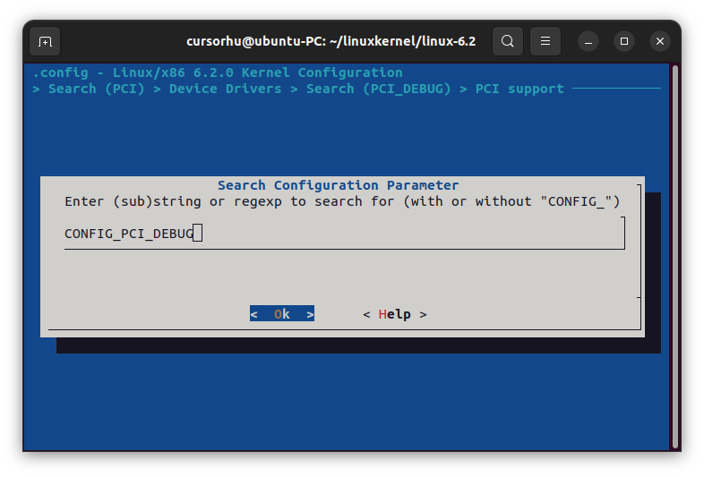
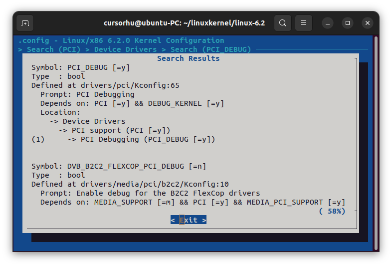
### Kconfig:
config PCI_DEBUG
bool "PCI Debugging"
depends on DEBUG_KERNEL
help
Say Y here if you want the PCI core to produce a bunch of debug
messages to the system log. Select this if you are having a
problem with PCI support and want to see more of what is going on.

When in doubt, say N.

最后设置printk level大于DEBUG level:

1
echo 8 > /proc/sys/kernel/printk

此后dmesg可查看drivers/pci下的所有pci_dbg都被打印(当然也包括pci_info, pci_err等)。

make menuconfig配置技巧

如何快速定位CONFIG项

以PCIe driver为例,drivers/pci的Makefile有以下CONFIG

1
subdir-ccflags-$(CONFIG_PCI_DEBUG) := -DDEBUG

现在make menuconfig时想快速定位CONFIG_PCI_DEBUG对应的位置再设置为y,定位操作如下:

step1: 输入/ 打开查找,输入要查找的CONFIG名,注意这里不支持模糊匹配

Screenshot from 2023-08-03 11-52-54

Screenshot from 2023-08-03 11-51-31

step2: 按1跳转到CONFIG对应位置

Screenshot from 2023-08-03 11-51-55

直接修改.config文件

make menuconfig本质是配置.config文件,可以手动修改CONFIG_XXX = y/m

Ftrace详解

ftrace是printk之外,能观测driver/kernel的函数(symbol)调用流程和执行时间的重要debug功能。

ftrace的系统框图如下,只需要配置用户空间暴露的trace文件,就可以读取kernel的trace buffer信息:

524572_1276915819YAfE

ftrace的完整使用教程和原理,参考:

Mastering Embedded Linux Programming

Linux Tracing Technologies

function_graph使用示例

在ftrace相关Kconfig和debugfs已开启情况下,如下是查询sleep调用了哪些function

1
2
3
4
5
6
7
sudo su	#用root操作debugfs
cd /sys/kernel/debug/tracing #进入tracing目录,方便操作trace文件
echo function_graph > current_tracer 当前tracer使用function_graph模式
echo 1 > tracing_on #开启trace
sleep 1 #执行要trace的操作
echo 0 > tracing_on #(可选)关闭trace
cat trace #查看trace的输出文件

部分关键函数调用流程如下:

1
2
3
4
5
6
7
8
9
10
11
12
13
14
15
16
17
18
19
20
21
22
23
24
25
26
27
28
29
30
31
32
33
34
35
36
37
38
39
40
41
42
43
44
45
46
47
48
49
50
51
52
53
54
55
56
57
58
59
60
61
62
# tracer: function_graph
#
# CPU DURATION FUNCTION CALLS
# | | | | | | |

3) | cpuidle_enter() {
3) 0.271 us | tick_nohz_get_next_hrtimer();
3) | cpuidle_enter_state() {
3) | leave_mm() {
3) | switch_mm() {
3) | switch_mm_irqs_off() {
3) 0.441 us | load_new_mm_cr3();
3) 0.299 us | switch_ldt();
3) 1.661 us | }
3) 2.193 us | }
3) 2.721 us | }
3) 0.271 us | sched_idle_set_state();
3) | intel_idle_ibrs() {
3) 0.273 us | spec_ctrl_current();
3) # 8916.545 us | }
3) 0.608 us | sched_idle_set_state();
3) | irq_enter_rcu() {
3) | tick_irq_enter() {
3) 0.394 us | tick_check_oneshot_broadcast_this_cpu();
3) 0.466 us | ktime_get();
3) 0.337 us | nr_iowait_cpu();
3) 0.379 us | tick_do_update_jiffies64();
3) 3.274 us | }
3) 3.996 us | }
3) | __common_interrupt() {
3) | handle_edge_irq() {
3) 0.348 us | _raw_spin_lock();
3) | irq_chip_ack_parent() {
3) 0.526 us | apic_ack_irq();
3) 1.275 us | }
3) | handle_irq_event() {
3) 0.332 us | _raw_spin_unlock();
3) | __handle_irq_event_percpu() {
3) | e1000_intr_msi [e1000e]() {
3) 0.322 us | napi_schedule_prep();
3) | __napi_schedule() {
3) 0.320 us | __raise_softirq_irqoff();
3) 0.982 us | }
3) 4.938 us | }
3) 5.759 us | }
3) | add_interrupt_randomness() {
3) 0.334 us | fast_mix();
3) 0.982 us | }
3) 0.340 us | note_interrupt();
3) 0.322 us | _raw_spin_lock();
3) 9.578 us | }
3) 0.323 us | _raw_spin_unlock();
3) + 13.112 us | }
3) + 13.883 us | }
3) | irq_exit_rcu() {
3) | __do_softirq() {
....
3) ! 135.293 us | }
3) 0.371 us | idle_cpu();
3) ! 136.785 us | }
3) # 9079.848 us | }
3) # 9080.993 us | }

cpuidle_enter源码对照一致

注意多个CPU的trace可能混杂,例如下面是CPU1和3交替执行:

1
2
3
4
5
6
7
8
9
10
11
12
13
14
15
16
17
18
19
# tracer: function_graph
#
# CPU DURATION FUNCTION CALLS
# | | | | | | |
1) | cpuidle_enter() {
1) 0.158 us | tick_nohz_get_next_hrtimer();
1) | cpuidle_enter_state() {
1) 0.174 us | leave_mm();
1) 0.158 us | sched_idle_set_state();
1) | intel_idle_ibrs() {
1) 0.158 us | spec_ctrl_current();
1) # 3924.061 us | }
3) # 7847.617 us | }
1) 0.337 us | sched_idle_set_state();
3) 0.323 us | sched_idle_set_state();
1) | irq_enter_rcu() {
1) | tick_irq_enter() {
3) | irq_enter_rcu() {
1) 0.210 us | tick_check_oneshot_broadcast_this_cpu();

trace函数的过滤(ftrace_filter)

查看有哪些symbol(function)可以作为trace过滤关键字,一般kernel和已加载的driver函数都在此列表中

1
2
cat available_filter_functions #查看所有symbol
cat available_filter_functions | grep pci #查看所有名字带pci的symbol

一个symbol list示例如下(grep pci),其中带[]的是Driver Module的symbol, 不带的为build-in kernel的symbol:

1
2
3
4
5
6
7
8
9
10
11
12
13
14
read_pci_config
read_pci_config_byte
write_pci_config
write_pci_config_byte
...
pciehp_probe
pciehp_configure_device
pciehp_isr
pciehp_ist
...
sdhci_pci_enable_dma [sdhci_pci]
sdhci_pci_remove_slot [sdhci_pci]
nvme_pci_complete_rq [nvme]
nvme_pci_enable [nvme]

trace带pci关键字的symbol,示例如下:

1
2
3
echo "" > trace #清空现有trace信息
echo "*pci*" > set_ftrace_filter #设置过滤关键字
echo 1 > /sys/bus/pci/rescan #执行trace操作:rescan所有pci设备

关键流程的trace输出如下,pci_scan_slot是rescan的核心操作:

1
2
3
4
5
6
7
8
9
10
11
12
13
14
1)               |      pci_scan_slot() {
1) | pci_scan_single_device() {
1) | pci_get_slot() {
1) 0.912 us | pci_dev_get();
1) 2.467 us | }
1) | pci_bus_generic_read_dev_vendor_id() {
1) | pci_bus_read_config_dword() {
1) | pci_read() {
1) 9.293 us | pci_conf1_read();
1) + 10.669 us | }
1) + 12.057 us | }
1) + 18.047 us | }
1) + 31.012 us | }
1) + 32.412 us | }

trace过滤的高级用法

假设想trace某个driver module的所有symbol, 如果仅靠函数关键字很难实现

解决办法:将available_filter_functions经过文本处理(sed/awk/grep)后,输出要trace的driver module的所有symbol列表,再写入set_ftrace_filter文件。

以下示例trace driver module名为bht_sd的所有symbol:

1
2
lsmod | grep bht_sd	#首先确认module已加载
cat available_filter_functions | grep bht_sd #查看module的symbol是否存在于available_filter_functions

grep bht_sd输出的部分symbol如下:

1
2
3
4
5
bht_sd_resume [bht_sd]
bht_sd_suspend [bht_sd]
bht_sd_pci_release [bht_sd]
bht_sd_remove [bht_sd]
bht_sd_probe [bht_sd]

用grep, awk过滤一下,只保留函数名,去掉[module名]

1
cat available_filter_functions | grep bht_sd | awk '{ print $1 }'

输出:

1
2
3
4
5
6
bht_sd_resume 
bht_sd_suspend
bht_sd_pci_release
bht_sd_remove
bht_sd_probe
...

再写入set_ftrace_filter(要一段时间),用一个命令处理:

1
cat available_filter_functions | grep bht_sd | awk '{ print $1 }' > set_ftrace_filter

查看set_ftrace_filter可见Driver module的symbol又添加了[module名],可能是ftrace_filter自己添加的索引信息

1
2
3
4
5
bht_sd_resume [bht_sd]
bht_sd_suspend [bht_sd]
bht_sd_pci_release [bht_sd]
bht_sd_remove [bht_sd]
bht_sd_probe [bht_sd]

对该Driver设备操作(例如device rescan),cat/vim trace输出正常:

1
2
3
4
5
6
7
8
9
2)               |    bht_sd_probe [bht_sd]() {
2) 2.516 us | os_memset [bht_sd]();
2) | DbgInfo [bht_sd]() {
2) 0.911 us | fls32 [bht_sd]();
2) 0.850 us | os_memcpy [bht_sd]();
2) 5.089 us | os_print [bht_sd]();
2) + 12.315 us | }
...

另外一种对.ko用nm命令输出symbol,参考:defeattroy/用Ftrace跟踪内核模块

在存储设备的windows系统环境下调试时,因为存储设备本身的问题,有时候coredump不能成功生成到系统目录,本文记录如何修改coredump路径,以及用键盘测试coredump生成符合预期。

使能windows的coredump

Enabling a Kernel-Mode Dump File

修改coredump路径

Windows 的内存转储文件选项概述

可以修改注册表HKEY_LOCAL_MACHINE\System\CurrentControlSet\Control\CrashControl的DumpFile键值对,默认路径%SystemRoot%在cmd echo出来是”C:", 修改为指定路径例如”E:\Memory.dmp”。

image-20230724155525547

此操作也可以在控制面板完成,两者等效。

crashcontrol2

使用键盘手动生成coredump

Forcing a system crash from the keyboard

以USB keyboards为例:

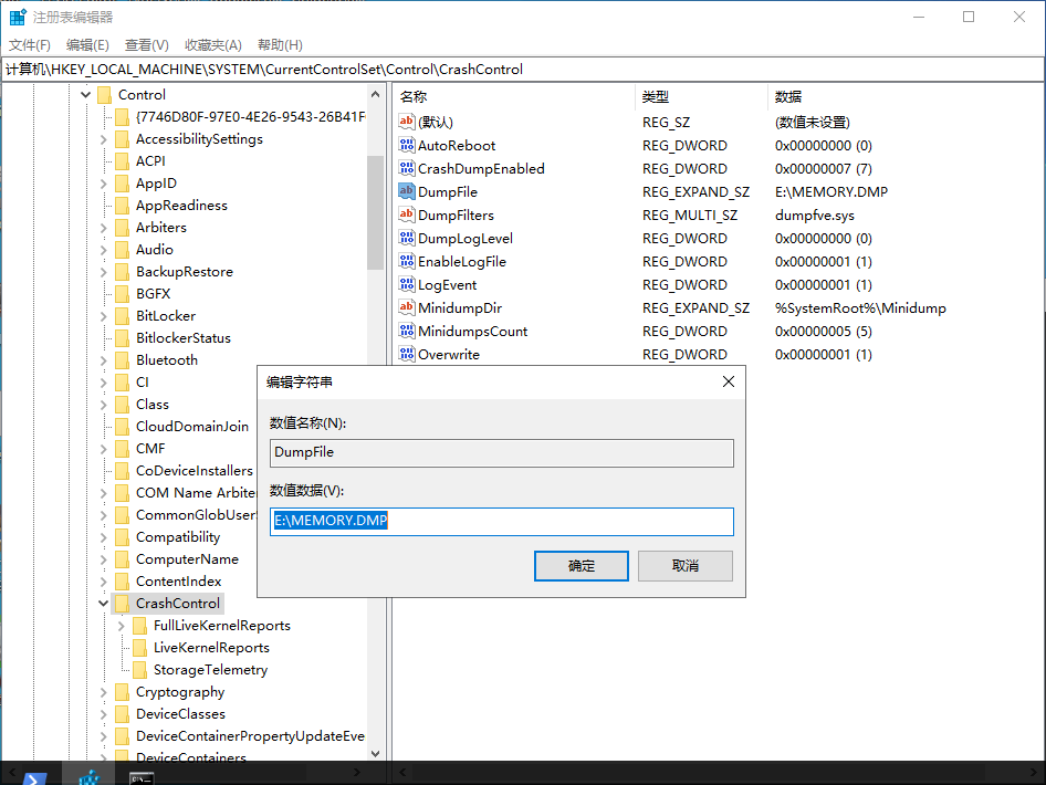
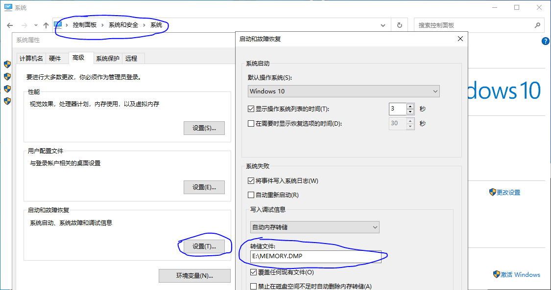
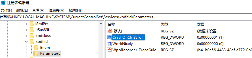
修改注册表HKEY_LOCAL_MACHINE\System\CurrentControlSet\Services\kbdhid\Parameters,创建CrashOnCtrlScroll = 0x01,重启后“Hold down the rightmost CTRL key, and press the SCROLL LOCK key twice.”系统会直接蓝屏,重启即可查看coredump文件。如果用windbg查看KeBugCheck查看错误码是0xE2: MANUALLY_INITIATED_CRASH。
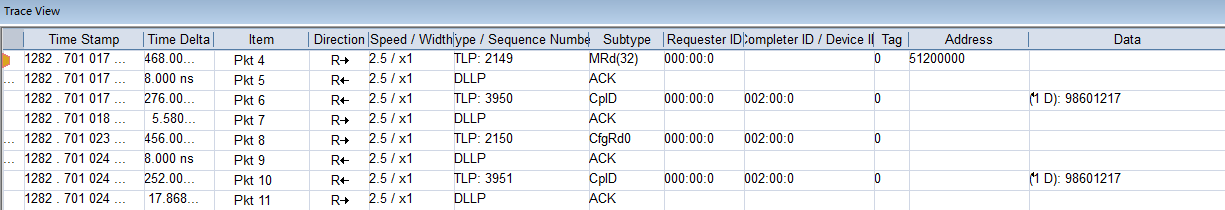
image-20230724155442525

前言

最近Debian12发布,尝鲜在移动硬盘装了Debian12+KDE,但不习惯Debian繁琐的包管理和Ubuntu越来越商业化的行为,最终切换到ArchLinux,进入Pacman和AUR的包管理和滚动更新风格。此文记录ArchLinux安装配置过程。

构建多系统的U盘启动盘

使用ventoy/Start to use Ventoy,将各系统镜像放到Ventoy目录即可,不需要用传统的UltraISO那种一个系统ISO要占用整个U盘。
Arch Linux的ISO在此下载

使用archinstall安装ArchLinux

传统的ArchLinux安装方式过于繁琐,现在Arch Linux安装包提供一个类GUI的脚本archinstall,按需求配置即可,可以一键处理包括KDE/GNOME/I3W等桌面在内的全部安装过程。

参考 使用 archinstall 自动化脚本安装 Arch Linux 完整指南使用 archinstall 安装 Arch Linux 和 KDE 桌面环境

我的配置如下。Profile选择安装desktop Kde, Network选择Use NetworkManager后,Kde Plasma被自动安装,不需要按参考文章手动安装桌面:

image-20230712164243209

配置主题

kde主题应用直接安装主题基本会失败,需要去KDE store下载主题并按主题的README配置

一个风格统一的主题包含几个部分:Global theme,包括桌面(desktop),图标(icon),鼠标(cursor),壁纸(wallpaper),也可以包含登录界面(sddm)和启动界面(GRUB)

(1)配置桌面

下面配置MacOS风格的 WhiteSur Dark,建议在Github下载完整主题:WhiteSur-kde

使用./install.sh安装主题,其内部操作就是拷贝各部分配置文件到系统配置目录:

1
2
3
4
5
6
7
8
cp -r ${SRC_DIR}/aurorae/normal/${name}${color}* ${AURORAE_DIR}
cp -r ${SRC_DIR}/Kvantum/${name} ${KVANTUM_DIR}
cp -r ${SRC_DIR}/wallpaper/${name}* ${WALLPAPER_DIR}
cp -r ${SRC_DIR}/latte-dock/* ${LATTE_DIR}
cp -r ${SRC_DIR}/color-schemes/* ${SCHEMES_DIR}
cp -r ${SRC_DIR}/plasma/desktoptheme/${name}${pcolor} ${PLASMA_DIR}
cp -r ${SRC_DIR}/plasma/desktoptheme/icons ${PLASMA_DIR}/${name}${pcolor}
...

其中的latte-dock只是配置文件,需要先安装latte-dock

1
yay -S latte-dock

主题安装完毕后,在系统System Setting -> Appearance -> Global Theme的子目录apply各模块

(2)配置登录界面

登录界面SDDM需要独立安装,在WhiteSur-kde的sddm目录运行install.sh安装sddm,之后可在系统System Setting -> Startup and Shutdown中设置sddm为WhiteSur。

(3)配置启动界面

Arch linux默认没有GRUB,需要安装GRUB

1
2
sudo pacman -S grub efibootmgr
sudo grub-install --target=x86_64-efi --efi-directory=/boot --bootloader-id=GRUB

Dark Matter GRUB Theme为例,按github的install guide安装即可。

GRUB配置文件位于/etc/default/grub,修改后使用update-grub生效。

中文显示和中文输入法

打开网页有中文乱码(方框),需要安装noto-fonts相关字体包

1
sudo pacman -S noto-fonts noto-fonts-cjk noto-fonts-emoji

安装中文输入法框架(包含pinyin输入法)并配置fcitx5,具体含义参考 Input method

1
sudo pacman -S fcitx5-im fcitx5-chinese-addons  fcitx5-rime

在desktop environment配置fcitx:

1
2
3
4
sudo vim /etc/environment
GTK_IM_MODULE=fcitx
QT_IM_MODULE=fcitx
XMODIFIERS=@im=fcitx

重启,按 Win 键搜索 Input Method, 点击 Add Input Method...搜索 pinyin 然后添加,按 Ctrl + 空格可切换输入法

安装yay以使用AUR

yay: Yet another yogurt. Pacman wrapper and AUR helper written in go.

yay的安装参考: How to Install yay AUR Helper in Arch Linux [Beginner’s Guide]

1
2
3
4
5
6
sudo pacman -S base-devel git
cd /opt
sudo git clone https://aur.archlinux.org/yay.git
cd yay
sudo chown -R 用户名:users . #必须修改yay目录的owner, yay不能被sudo编译
makepkg -si #编译yay

Go语言包换源

安装yay时makepkg会显示go包安装timeout, 需要换国内源 goprixy.cn

1
2
3
4
5
6
7
8
#临时生效
$ export GO111MODULE=on
$ export GOPROXY=https://goproxy.cn

#永久生效
$ echo "export GO111MODULE=on" >> ~/.profile
$ echo "export GOPROXY=https://goproxy.cn" >> ~/.profile
$ source ~/.profile

pacman/yay换源

在archinstall时如果Mirror region选择China,则默认使用官方提供的China源,见/etc/pacman.conf的[core/extra]字段都版本了/etc/pacman.d/mirrorlist.

但官方源速度有时很慢,建议手动添加archlinuxcn源,如果包在国内源有的话,yay速度直接起飞

有网上建议生成aur配置文件换国内源:yay --aururl “https://aur.tuna.tsinghua.edu.cn” --save 此处不建议,如果国内源没有的包将无法下载;换回官方源:yay --aururl "https://aur.archlinux.org" --save,并删除yay源配置文件~/.config/yay/config.json

yay常用命令

从仓库和 AUR 中交互式搜索和安装软件包:

1
yay {{软件包|搜索词}}

同步并更新所有来自仓库和 AUR 的软件包:

1
yay

从仓库和 AUR 中安装一个新的软件包。

1
2
yay -S {{软件包}}
yay -Sy {{软件包}} #默认yes

从仓库和 AUR 中搜索软件包数据库中的关键词:

1
yay -Ss {{关键词}}

显示已安装软件包和系统健康状况的统计数据:

1
yay -Ps

卸载包:

1
yay -R 

pacman更新系统

更新所有安装包:

1
2
sudo pacman -Syu #仅更新
sudo pacman -Syyu #如果系统有损坏包,能覆盖下载

Host DNS设置

NetworkManager会自动配置DNS域名解析文件/etc/resolv.conf,且手动修改的内容每次重启会被NetworkManager覆盖。

如果要手动配置,参考 /etc/resolv.conf,设置dns.conf:

1
2
3
/etc/NetworkManager/conf.d/dns.conf
[main]
dns=none

KDE Discover显示unable to load applications

1
sudo pacman -S packagekit-qt5

安装kernel编译环境

1
sudo apt install build-essential libncurses-dev bison flex libssl-dev libelf-dev

安装bear

1
sudo apt install bear

使用bear编译kernel,生成compile_commands.json,参考:Ubuntu22 直接 make 内核成功,但不能使用 bear 命令

1
bear -- make -j4

在编译Kernel的源代码环境安装clangd服务端:

1
sudo apt install clangd

在查看代码的VSCode环境安装clangd客户端(即VSCode的clangd插件):一般通过windows机器的VSCode SSH连接Linux的clangd服务,因此需要将VSCode的remote SSH登陆到Linux机器(注意不要同时使用Xshell等其他SSH工具,否则VSCode remote SSH连不上)

VSCode remote SSH中打开代码后,clangd自动indexing(完成Kernel index需要相当长时间),CTRL+鼠标左键查看定义,ALT+左键头返回跳转

clangd方式可以很方便找到C函数指针的实现,而VSCode的C++ intellisense跳转不到

参考:使用VSCode进行linux内核代码阅读和开发